

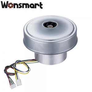
Key Takeaways
- Because vacuum adsorption workholding relies on atmospheric pressure differential, the suction force available to hold a workpiece equals pressure differential (kPa) multiplied by pad area — so undersizing pressure means undersizing holding force.
- Most CNC machining center applications require -25kPa to -35kPa gauge vacuum at the chuck interface under dynamic cutting loads; a blower that only delivers -15kPa will chatter, slip, or drop parts during heavy passes.
- Airflow sizing (m³/h) must account for **system leakage rate plus the volume that must be evacuated per evacuation cycle** — a blower sized only for steady-state vacuum will have excessively long pump-down times.
- For mobile or portable automation equipment, 24V blowers simplify power architecture; for fixed CNC cells with 48V bus available, 48V blowers deliver higher pressure ratio per stage and better efficiency at target rpm.
Most automation engineers who specify vacuum adsorption components have been through this: you size the vacuum chuck, calculate the required suction force, select a blower that seems to match the vacuum pressure spec, and then the part slips during the first heavy cutting pass. Or the pump-down cycle takes 45 seconds instead of the 15 seconds your cycle time budget allows. The root cause is almost always the same — the blower was sized around a single vacuum pressure number, without accounting for the dynamic pressure drop under load, the system’s total leakage rate, or the actual volume that must be evacuated on every cycle.
In my work supporting automation equipment OEMs on motor specification alignment, I have seen these sizing errors cost manufacturers thousands in scrap parts, rework time, and integration debugging. So in this article, I am going to walk you through the complete suction force-based sizing methodology that automation engineers should apply before selecting any vacuum adsorption blower — the three parameters you must define first, the calculation steps, a practical voltage selection framework, and the five sizing mistakes I see most often on the shop floor.
Why Suction Force Calculation Is the Foundation of Vacuum System Design
Vacuum adsorption workholding works by removing air from the space between a flat suction pad and the workpiece surface. Because atmospheric pressure pushes down at approximately 101.3 kPa absolute, and the space under the pad is evacuated to a lower pressure, the resulting pressure differential creates a holding force perpendicular to the workpiece surface. The mathematics are straightforward — suction force equals pressure differential multiplied by the effective pad area — but the engineering challenge is that the actual pressure differential at the pad is almost always lower than the blower’s rated maximum vacuum, and it drops further under the dynamic forces of a cutting operation.
When we talk to automation engineers after they have experienced a workholding failure, the pattern is almost always the same: they sized their system using the blower’s rated maximum vacuum pressure, without accounting for three real-world factors that systematically reduce effective suction force. So the first principle of suction force-based motor sizing is this: always design to the minimum pressure differential you will experience under load, not the rated maximum vacuum of the equipment.
Three Core Parameters Every Automation Engineer Must Define Before Selecting a Blower
Before you look at a single blower datasheet, you need to have three numbers defined from your application. These are not blower specifications — they are the inputs to the sizing calculation.
1. Required Suction Force (in Newtons)
Because cutting forces in machining operations act as a direct counter-force to the vacuum holding force, the required suction force must at minimum equal the maximum cutting force your operation generates, multiplied by a safety factor. For most CNC milling operations on aluminum or steel, we recommend a minimum safety factor of 2.0x — meaning the vacuum system must be capable of holding twice the measured cutting force at the worst-case feed rate and depth of cut.
Calculate it this way: if your machining operation generates up to 2000 N of cutting force in the worst axis, and you are using four vacuum pads, each pad must sustain at minimum 500 N of holding force. That is your starting point for every subsequent calculation in the sizing process.
2. Vacuum Pad Area (in cm²)
The effective area of your vacuum pad is not the geometric footprint — it is the area of the flexible sealing lip that actually forms the vacuum chamber when compressed against the workpiece surface. For a standard round pad with a 100mm diameter and a 10mm-wide sealing lip, the effective vacuum chamber area is approximately the inner circle minus the lip width — roughly 50 cm² to 60 cm² for a pad of this size. Always measure your actual sealing lip width under compression before calculating, because lip compression from clamping force can reduce effective area by 10–15% compared to the nominal dimension.
3. System Volume and Allowable Evacuation Time (m³ and seconds)
The evacuation time is determined by two factors: the total internal volume of your vacuum circuit — including the chamber under the pad, the connecting tubing, and any distribution manifolds — and the blower’s actual airflow capacity at the vacuum level you need. A blower rated at 55 m³/h sounds large, but that is its open-flow (zero pressure) rating. At -30kPa, the actual airflow may be 30–40% lower due to the compressor’s characteristic curve. Always pull airflow data from the performance curve at your target vacuum pressure, not from the headline number.
How to Calculate the Minimum Vacuum Pressure for Your Workholding Application
Once you have defined the three core parameters above, the minimum vacuum pressure calculation is straightforward arithmetic.
Required Pressure (kPa) = Cutting Force (N) / Number of Pads / Pad Area (cm²)
Step 2 — Apply Safety Factor:
Design Pressure (kPa) = Required Pressure x 2.0 (safety factor)
Example: 2000N cutting force, 4 pads, 55cm² effective area each
Required Pressure = 2000 / 4 / 55 = 9.1 kPa per pad
Design Pressure = 9.1 x 2.0 = 18.2 kPa minimum gauge vacuum
Recommendation: Select a blower rated for -25kPa to -35kPa gauge to provide margin for dynamic force peaks and motor speed variation over lifetime.
Because the vacuum pressure under the pad is a function of the pressure drop across the system — including the drop through the connecting tubing, the manifold, and any filters — you need to add a pressure drop allowance of approximately 3–5 kPa for the piping circuit. This means the blower must generate slightly more vacuum at its outlet than the pad requires, to account for losses in the delivery system.
What About Pads With Multiple Chambers?
Some vacuum chuck designs use segmented pads with independent chambers, each connected to a separate vacuum circuit. Because each chamber acts as an independent adsorption zone, you must calculate the required vacuum pressure for each chamber type separately. In segmented designs, a failure in one chamber does not always cause complete workpiece release — but it does reduce the total holding force proportionally, so design your system with enough margin that a single-chamber failure does not drop the safety factor below 2.0x.
Airflow Sizing: Matching Blower Capacity to Chamber Volume and Cycle Time
Pressure and airflow are related but distinct specifications, and both are required for a complete sizing. Pressure determines whether the system can hold the workpiece under load; airflow determines how quickly the system reaches operating vacuum after each workpiece change. An undersized airflow spec does not cause immediate part slips — it causes slow cycle times that erode the productivity advantage of the machining center.
Pump-Down Time (s) = (System Volume m³ x 2.303 x log₁₀[101.3 / (101.3 - Target Vacuum kPa)]) / (Blower Airflow m³/h at target vacuum x (1 – Leakage Fraction))
Example: System volume = 0.005 m³, target vacuum = -30kPa, allowable pump-down = 15s, estimated leakage = 12%
Numerator = 0.005 x 2.303 x log₁₀[101.3 / 71.3] = 0.005 x 2.303 x 0.152 = 0.00175
Denominator = (Airflow m³/h at -30kPa x 0.88) / 3600
Solving for airflow: Airflow needed ≈ 28 m³/h at -30kPa
Always verify airflow at the actual target pressure — not the blower’s open-flow rating. Ask the supplier for the performance curve.
System leakage is the most commonly underestimated factor in airflow sizing. Because vacuum adsorption chucks operate with flexible sealing lips compressed against imperfectly flat workpiece surfaces, some air leakage is inevitable. The leakage rate depends on the sealing lip material (silicone lips generally seal better than rubber at the cost of lower chemical resistance), the flatness of the workpiece surface, and the clamping force applied to compress the lip. For a new system with well-prepared workpieces, plan for 8–12% leakage. For rough castings or milled surfaces that are not re-faced, plan for up to 20%.
24V vs 48V Blower for Vacuum Adsorption: A Practical Decision Framework
The voltage choice is often treated as an afterthought, but it has real implications for both system architecture and performance. Because brushless DC motor efficiency and torque output are both a function of the voltage applied relative to the motor’s design point, selecting the right voltage for your application is part of the sizing process, not a separate decision.
| Parameter | 24V Blower | 48V Blower |
|---|---|---|
| Max Static Pressure | Up to -5.0 kPa (standard series) | Up to -7.0 kPa or higher per stage |
| Best For | Portable/mobile equipment, 24V power bus, battery-powered systems | Fixed CNC cells, 48V bus available, deep vacuum (-40kPa+) |
| Efficiency at Target RPM | Good at low-to-mid pressure range | Higher efficiency at sustained high-rpm, high-pressure operation |
| Power Architecture | Direct from 24V supply, no boost converter needed | May require 48V bus or external power stage |
| Typical CNC Machining Application | Suitable for -20kPa to -30kPa range | Suitable for -30kPa to -50kPa range |
For most standard CNC machining center vacuum adsorption applications, both 24V and 48V blowers are viable options in the -25kPa to -35kPa pressure range. The decision should be driven by your existing power infrastructure and the maximum depth of vacuum you need. If your facility already has 48V distribution in the machine tool cabinet, going with a 48V blower eliminates the cost and complexity of a voltage conversion stage. If you are building a portable or battery-powered workholding fixture, the 24V option is more practical.
Sizing Worksheet: Step-by-Step Motor Selection for Vacuum Adsorption Systems
Here is the complete sizing sequence we walk our OEM customers through when they come to us with a new vacuum adsorption project. Work through each step in order — skipping steps leads to sizing errors.
Step 1: Define Application Parameters
- Maximum cutting force (N) in the most critical axis — use your CAM software or a force model to estimate this at the deepest depth of cut and highest feed rate.
- Number of vacuum pads to be used simultaneously.
- Effective area of each pad sealing lip under compression (cm²) — measure directly, do not use nominal dimensions.
- Total internal volume of vacuum circuit (m³) — include manifold, tubing, and pad chambers.
- Allowable pump-down time per workpiece change (seconds).
Step 2: Calculate Required Vacuum Pressure
Apply the formula above: (Cutting Force / Pads / Pad Area) x 2.0 safety factor. Add 3–5 kPa for piping circuit pressure drop. The result is the minimum gauge vacuum pressure the blower must be able to sustain continuously at the pad.
Step 3: Calculate Required Airflow
Use the pump-down formula above. Identify your target vacuum pressure from Step 2, use your system volume and allowable pump-down time, and estimate your leakage fraction based on workpiece surface quality. Look up the airflow at your target vacuum pressure on the supplier’s performance curve — not the headline number.
Step 4: Verify Max Static Pressure
Select a blower whose maximum static pressure specification exceeds your design vacuum pressure by at least 20%. Because motor speed varies with supply voltage tolerance and bearing wear over time, a blower rated at -35kPa maximum may only produce -30kPa at the low end of its voltage tolerance after 5000 hours of operation. The 20% margin accounts for this degradation path.
Step 5: Verify Bearing Life
Confirm the bearing life specification in hours at your target operating speed and ambient temperature. We recommend a minimum of 15000 hours for CNC machining center applications, which typically corresponds to several years of operation in a production environment. Ask for the supplier’s bearing life test data, not just the theoretical calculation.
Step 6: Check Electrical Interface Compatibility
Verify that the blower’s control interface (PWM, 0–5V analog, or CAN bus) is compatible with your PLC or CNC controller. If you are retrofitting into an existing machine, the control interface compatibility is often the dimension that eliminates otherwise suitable blower candidates.
Common Sizing Mistakes That Cause Vacuum Workholding Failures on the Shop Floor
After supporting hundreds of vacuum adsorption installations, the failures cluster into a small number of predictable root causes. Here is the list I wish every automation engineer had before their first vacuum workholding commissioning.
Mistake 1: Sizing to Rated Maximum Vacuum Instead of Actual Pressure Under Load
The most common error. A blower rated at -40kPa maximum vacuum will only produce -30kPa at its optimal operating point, and it will produce even less — perhaps -22kPa — when connected to a system with piping losses, flow restrictions, and leakage. Because cutting force calculations are precise, but the vacuum pressure used in those calculations must be the actual sustained pressure under load, sizing to the rated maximum systematically undersizes your system.
Mistake 2: Ignoring the Leakage Rate in Airflow Sizing
A blower that can flow enough air to evacuate the clean system volume in 12 seconds will take 20+ seconds if the actual leakage rate is 30% instead of the estimated 10%. Because most vacuum chucks are specified for a range of workpiece surface conditions, the leakage assumption should always be based on the worst-case surface you will run, not the ideal surface.
Mistake 3: Using Peak Airflow Instead of Flow at Target Vacuum Pressure
The headline airflow number on a blower datasheet is the open-flow value — measured when there is zero pressure differential across the inlet and outlet. At -30kPa operating vacuum, the actual flow is typically 30–50% lower than the open-flow rating. I have seen systems that were specified with a blower that had a datasheet rating of 55 m³/h open flow, only to find that the actual flow at -30kPa was 28 m³/h — insufficient for the target pump-down time.
Mistake 4: Not Verifying Max Static Pressure Margin
Selecting a blower whose maximum static pressure exactly matches your target vacuum means you have zero margin for motor speed variation, component wear, or temperature drift. Always verify that the maximum static pressure specification exceeds your design vacuum by at least 20%. This is not engineering conservatism — it is accounting for the fact that real components operate within tolerance bands, not at their nominal values.
Mistake 5: Overlooking Bearing Life at Target Operating Conditions
Bearing life specifications in blower datasheets are typically stated at nominal speed and room temperature. In a CNC enclosure, ambient temperatures can reach 45–50 degrees Celsius during extended cutting operations, and the motor winding temperature adds another 20–30 degrees above ambient. At elevated temperatures, bearing grease viscosity drops and bearing life shortens significantly. Ask the supplier for bearing life derating curves at elevated temperature before you commit.
Need a Vacuum Adsorption Blower Technical Consultation?
Wonsmart’s engineering team supports automation OEMs with blower selection, suction force calculation, and integration fit verification. Contact our technical team to discuss your vacuum adsorption sizing requirements.
About the Author
Mr. Dong serves as Technical Director at Ningbo Wonsmart Motor Fan Co., Ltd., leading brushless DC blower engineering and application support across medical, industrial, and laser equipment sectors. He works closely with OEM customers on motor specification alignment, integration fit verification, and compliance documentation for IEC 60601-1 medical devices and industrial EMC / RoHS / REACH standards.


