

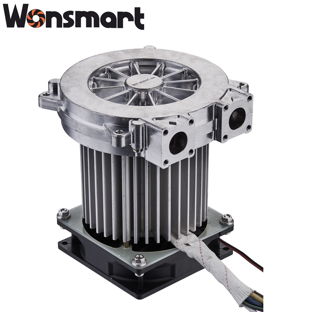
Why Hydrogen Stack OEMs Are Switching to Brushless DC Blowers
The fuel cell blower is one of the most failure-prone components on a hydrogen fuel cell stack, and the choice between brushed and brushless DC architecture decides how often the stack goes down for service. Brushed DC blowers were the standard on the first generation of small stationary fuel cells, and the field data from those systems is what is driving the current switch to brushless DC across the hydrogen stack industry.
Brushed DC blowers use a commutator and carbon brushes to switch the current in the rotor windings. The mechanical contact between the brush and the commutator is what wears out. On a continuous-duty fuel cell application, the brush life is typically 1,500-2,500 hours before the brush needs replacement. On an intermittent-duty fuel cell with frequent start-stop cycles, the brush life can drop below 1,000 hours because the inrush current at each start accelerates brush wear. The result is a service interval on the blower that is shorter than the service interval on the stack itself.
Brushless DC blowers eliminate the brush and the commutator. The rotor is a permanent magnet, and the stator windings are switched electronically by an integrated driver. The only wear-out mechanism in a brushless DC blower is the bearing, and a high-quality NMB ball bearing has a calculated L10 life of 20,000-30,000 hours at the rated speed and load. The blower therefore lasts longer than the stack, which means the blower no longer drives the stack service interval. For a fuel cell OEM designing a stack for 10,000+ hours of operating life, the brushless DC blower is the right architecture.
What a Fuel Cell Blower Actually Does: Air Supply, Pressure Ratio, and Humidity Control
A fuel cell blower has three core functions on a hydrogen stack: deliver the air supply to the cathode side of the membrane electrode assembly, maintain the pressure ratio that drives the air through the membrane, and control the humidity of the incoming air so the membrane stays within its moisture operating band.
Air supply is the primary function. A proton exchange membrane (PEM) fuel cell needs a stoichiometric excess of air at the cathode — typically 1.5-2.5 times the air that is chemically consumed by the reaction. The blower has to deliver that excess reliably across the full power range of the stack, from idle at 5-10% of rated power to full power at 100%. A blower that can deliver 5 CFM at idle and 50 CFM at full power without surging is the design target.
Pressure ratio is the second function. The cathode side of the membrane operates at a slight overpressure relative to ambient, typically 30-80 kPa gauge pressure depending on the stack pressure class. The blower has to develop that overpressure against the membrane back-pressure. A 3 kW stack typically runs at 20-30 kPa gauge; a 5 kW stack at 25-32 kPa; a 10 kW stack at 30-35 kPa. The blower pressure ratio is what sets the maximum stack current density the system can sustain without voltage collapse.
Humidity control is the third function. The membrane needs to stay within a moisture band of typically 60-90% relative humidity at the operating temperature. Too dry and the membrane conductivity drops and the stack voltage collapses. Too wet and the cathode floods and the air supply is blocked. The blower interacts with the membrane humidifier section to keep the air stream within the band, and the blower speed is the primary control knob on most modern stack control architectures. A blower that accepts a 0-10V or PWM speed command from the stack controller is the standard configuration.
Brushed vs. Brushless DC: 5 Failure Modes That Drive the Switch
Five failure modes account for the field data that drives the switch from brushed to brushless DC blowers on hydrogen stack duty. Each failure mode maps to a specific component on the brushed DC blower that is eliminated on the brushless DC architecture.
Failure mode one: commutator brush wear. The carbon brush on a brushed DC blower is a wear part with a finite life. On continuous-duty fuel cell operation, the brush typically lasts 1,500-2,500 hours. On intermittent-duty with frequent starts, the brush life drops below 1,000 hours. The brushless DC blower has no brush, which eliminates this failure mode entirely.
Failure mode two: brush dust contamination. As the carbon brush wears, it produces fine conductive dust that enters the air stream. On a fuel cell application, the dust enters the cathode air supply and deposits on the membrane surface. Over time, the deposit blocks the active area of the membrane and reduces the stack output. The brushless DC blower eliminates the source of the dust.
Failure mode three: low efficiency. A brushed DC blower has a typical efficiency of 40-50% because of the I²R loss in the brush contact and the rotor winding. A brushless DC blower has a typical efficiency of 70-80% because the electronic commutation eliminates the brush contact loss. The efficiency gap means the brushed blower draws more current from the stack balance-of-plant for the same air delivery, which reduces the net system efficiency.
Failure mode four: EMI/RFI from brush arcing. The mechanical commutation on a brushed DC blower produces electrical arcing at each commutation event. The arcing radiates EMI/RFI that interferes with the stack control electronics, the CAN bus, and the sensor signals. Brushless DC commutation is silent (no arcing) and produces no EMI/RFI beyond the switching noise of the driver itself, which can be filtered.
Failure mode five: lack of speed control feedback. A brushed DC blower on a simple voltage-control circuit runs at a speed that is set by the supply voltage and the load. The actual speed drifts with the load, the temperature, and the brush wear. A brushless DC blower with an integrated speed sensor (Hall sensor or encoder) provides closed-loop speed control and accepts a 0-10V, PWM, or CAN bus speed command from the stack controller. The closed-loop control is what enables the modern humidity control algorithms on the cathode side.
Brushless DC Efficiency: 75% vs. 45% and Why It Matters for Stack Output
The efficiency gap between brushed DC (40-50%) and brushless DC (70-80%) is not just a motor-engineering number. It has direct consequences on the fuel cell stack output and on the system balance-of-plant design. The blower draws power from the same source as the stack, and the parasitic load of the blower reduces the net power available from the system.
For a 5 kW stack with a blower that draws 200 W at full power, the parasitic load is 4% of the stack output. If the blower efficiency drops from 75% to 45%, the blower must draw 333 W to deliver the same airflow. The additional 133 W of parasitic load is energy that the fuel cell has to produce but the system cannot deliver to the load. The net stack output drops from 4,800 W to 4,667 W, which is a 2.7% reduction in net system efficiency.
For a 10 kW stack with a blower that draws 400 W at full power, the parasitic load is also 4% of the stack output, but the absolute number is 400 W vs. 667 W. The efficiency gap translates to a 267 W difference in net system output, which is significant on a stationary power system where the balance-of-plant has to fit within a fixed thermal envelope. The brushless DC blower is the standard configuration on modern stationary and mobile fuel cell systems for this reason.
Lifetime: 20,000 Hours vs. 2,000 Hours and Stack Service Interval
The 10x lifetime advantage of brushless DC over brushed DC on fuel cell duty (20,000 hours vs. 2,000 hours) is what most directly drives the procurement decision. The stack service interval on a PEM fuel cell is typically 10,000-15,000 hours for the membrane electrode assembly, and the blower service interval on a brushed DC architecture is shorter than the stack service interval. The blower becomes the limiting component on the system.
A brushless DC blower with NMB ball bearings and Class F or H windings has a calculated lifetime of 20,000-30,000 hours at the rated operating point. The lifetime is bounded by two mechanisms: bearing fatigue (L10 life of the ball bearing) and winding insulation aging (Arrhenius model on the insulation thermal class). Both mechanisms are predictable, and the blower supplier can size the bearings and the windings for the application duty cycle.
For an OEM specifying a brushless DC blower, the duty cycle on the RFQ should include: continuous vs. intermittent operation, ambient temperature, target lifetime in hours, and the speed profile (constant speed vs. variable speed with the stack power demand). A blower supplier that publishes lifetime test data for the specific duty cycle is the right partner; a blower supplier that only publishes the calculated bearing life is leaving the application risk on the OEM. Reference the ISO 13485 quality management standard for medical device manufacturers as the benchmark for blower supplier quality systems.
6 Specifications to Specify in a Fuel Cell Blower RFQ
Six specifications must appear on every fuel cell blower RFQ. Each specification maps to a different design constraint on the blower and a different verification test on the production blower.
Specification one: rated voltage. The standard voltages on a fuel cell blower are 12V, 24V, and 48V DC. 48V is increasingly the standard for fuel cell applications because the higher voltage reduces the cable gauge for the same power and improves the system efficiency. 36V and 72V are also used on some stack architectures.
Specification two: airflow at rated pressure. The airflow is typically specified in CFM (cubic feet per minute) or m³/h, at a specified gauge pressure. A 5 kW stack typically needs 10-15 CFM at 25-32 kPa gauge; a 10 kW stack typically needs 15-25 CFM at 30-35 kPa; a 3 kW stack typically needs 5-10 CFM at 20-30 kPa.
Specification three: maximum continuous pressure. The maximum continuous pressure rating is the highest gauge pressure the blower can sustain without damage. For a fuel cell application, the maximum continuous pressure is typically 1.5-2x the rated operating pressure to give a margin against transient pressure spikes from the stack.
Specification four: speed control interface. The standard speed control interfaces are 0-10V analog, PWM, and CAN bus. 0-10V is the simplest and is used on smaller stacks; PWM is the standard on mid-sized stacks; CAN bus is the standard on automotive and large stationary stacks. The interface must be specified on the RFQ because the blower driver design is different for each.
Specification five: IP rating. The IP rating is the ingress protection rating against dust and water. IP54 is the standard for indoor stationary fuel cells; IP65 is the standard for outdoor, under-hood, or marine fuel cells. The IP rating drives the bearing seal design and the housing design.
Specification six: duty cycle and lifetime target. The duty cycle is specified as continuous hours per day or as intermittent cycles per hour. The lifetime target is specified in hours. A blower supplier that publishes lifetime test data for the specific duty cycle is the right partner.
3 kW, 5 kW, 10 kW Stack Sizing: How Blower Power Maps to Stack Output
Three stack power classes cover the majority of stationary and mobile fuel cell applications. The blower power and airflow scale with the stack output, and the sizing rule is straightforward.
| Stack Power | Typical Airflow | Typical Gauge Pressure | Typical Blower Speed | Typical Voltage |
|---|---|---|---|---|
| 3 kW | 5-10 CFM | 20-30 kPa | 15,000-20,000 RPM | 24V or 48V DC |
| 5 kW | 10-15 CFM | 25-32 kPa | 15,000-20,000 RPM | 48V DC |
| 10 kW | 15-25 CFM | 30-35 kPa | 15,000-22,000 RPM | 48V DC |
| 30 kW and above | 50+ CFM | 50-80 kPa | Variable speed drive | 48V-96V DC |
The table makes the scaling explicit. From 3 kW to 10 kW, the airflow roughly triples, the gauge pressure rises by 5-10 kPa, and the blower speed stays in the same 15,000-22,000 RPM band. The blower power consumption scales from roughly 100 W at 3 kW to 400 W at 10 kW. For stacks above 30 kW, the blower architecture typically moves to a variable-speed drive with a higher voltage bus, which is outside the scope of a small brushless DC blower.
The Wonsmart fuel cell blower product line includes blowers sized for 3 kW, 5 kW, and 10 kW stacks, all built on the same brushless DC centrifugal architecture with NMB ball bearings and 48V DC nominal voltage. The WS145110-48-150-X300-SR is the 10 kW configuration with 32 kPa pressure and 15 CFM airflow.
Compliance: IEC 60601-1, EMC, RoHS, REACH for Fuel Cell Applications
Four compliance categories apply to a fuel cell blower on a stationary or mobile hydrogen system. Each category has specific standards that the blower must meet and specific documentation that the blower supplier must provide.
Compliance one: electrical safety. IEC 60601-1 applies to medical-grade fuel cell systems (hospital backup power, mobile medical carts). IEC 60950-1 or the newer IEC 62368-1 applies to industrial and stationary fuel cell systems. The blower must meet the creepage, clearance, and dielectric strength requirements of the applicable standard.
Compliance two: electromagnetic compatibility. IEC 61000-4-2 (electrostatic discharge), IEC 61000-4-3 (radiated RF immunity), IEC 61000-4-4 (electrical fast transient / burst), and IEC 61000-4-6 (conducted RF immunity) apply to the blower as part of the fuel cell system. The brushless DC architecture has a natural EMC advantage over the brushed DC architecture because there is no brush arcing, but the switching noise from the driver still has to be filtered.
Compliance three: RoHS. EU 2015/863 (RoHS 3) restricts the use of lead, mercury, cadmium, hexavalent chromium, and certain phthalates in electrical and electronic equipment. A fuel cell blower exported to the EU must comply with RoHS 3, and the blower supplier must provide a compliance declaration.
Compliance four: REACH. EC 1907/2006 (REACH) governs the registration, evaluation, authorization, and restriction of chemical substances. A fuel cell blower exported to the EU must comply with REACH, and the blower supplier must provide a declaration of compliance for the materials used in the blower.
The Wonsmart blower product line is manufactured under ISO 9001 and ISO 13485 quality management systems and carries ETL, CE, ROHS, and REACH certifications. About 60% of Wonsmart’s production is exported to North America, the EU, Japan, and Korea. The compliance documentation is available on request.
OEM Customization at Wonsmart: 48V/24V/12V Voltage, RPM, Connector, IP Rating
Ningbo Wonsmart Motor Fan Co., Ltd. (Wonsmart) was founded in 2009 and operates a 2,000 m² manufacturing facility in Ningbo. The factory specializes in small brushless DC motors and brushless DC blowers for medical, industrial, and laser equipment applications, with 15+ years of blower manufacturing experience. The product line covers air cushion, fuel cell, medical, environmental analyzer, and inflatable applications.
For a fuel cell blower RFQ, the OEM brief specifies six things: rated voltage (12V, 24V, 48V DC standard; 36V and 72V available), rated speed (10,000-25,000 RPM depending on the pressure ratio and flow target), airflow and pressure at the rated point, connector type (JST, Molex, or terminal block), control interface (0-10V analog, PWM, CAN bus, or RS-485), and IP rating (IP54 for indoor, IP65 for outdoor / under-hood). The factory also supports custom housing materials (aluminum, plastic, or stainless steel for harsh environments) and custom blade geometry for specific pressure-flow targets.
The factory’s standard fuel cell blower configurations include the fuel cell blower category page on its product catalog. Three power classes are available: a 3 kW mini turbo blower, a 5 kW mini turbo blower, and a 10 kW mini turbo blower, all built on the same brushless DC centrifugal architecture. For a brand specifying a private-label fuel cell blower, a 50-200 piece MOQ is typical for a fully custom configuration, with samples available in 2-4 weeks and production tooling in 6-8 weeks.
Conclusion: Building a Fuel Cell Blower Specification for Your Stack Family
For a hydrogen stack family that will be produced for the next 5 years, the right fuel cell blower specification starts with the brushless DC architecture and then sets the rated voltage, airflow, gauge pressure, speed control interface, IP rating, and lifetime target for the application. The 5 failure modes that drive the switch from brushed DC are brush wear, brush dust, low efficiency, EMI/RFI, and lack of speed control feedback. The compliance matrix that applies to the blower includes IEC 60601-1 (medical), IEC 62368-1 (industrial), IEC 61000-4-2/4-3/4-4/4-6 (EMC), RoHS 3, and REACH.
Send the fuel cell blower RFQ to a brushless DC blower OEM such as Ningbo Wonsmart Motor Fan specifying the stack power class (3 kW, 5 kW, 10 kW, or above), the rated voltage, the airflow and pressure target, the speed control interface, and the IP rating. The factory can quote a 50-200 piece MOQ for a fully custom fuel cell blower and provide a sample for field evaluation before committing to a full shipment.
Get a Fuel Cell Blower RFQ Reviewed
Ningbo Wonsmart Motor Fan Co., Ltd. (Wonsmart Motor Fan) is a 17-year OEM/ODM manufacturer of small brushless DC motors and brushless DC blowers, located in Ningbo, China. The factory operates a 2,000 m² facility and produces blowers with max airflow of 400 m³/h and max pressure of 60 kPa, with a calculated lifetime of 20,000+ hours. The fuel cell blower product line covers 3 kW, 5 kW, and 10 kW stack power classes, with rated voltages of 12V, 24V, and 48V DC, and NMB ball bearings as standard. The factory is certified to ISO 9001 and ISO 13485, and the blowers carry ETL, CE, ROHS, and REACH compliance for export to North America, the EU, Japan, and Korea. About 60% of Wonsmart’s production is exported. Submit your fuel cell blower RFQ specifying stack power class, voltage, airflow, pressure, control interface, and IP rating to Wonsmart’s application engineering team for a custom configuration review.
Frequently Asked Questions
Q1. Why are hydrogen stack OEMs switching to brushless DC blowers?
Hydrogen stack OEMs are switching to brushless DC blowers because brushed DC blowers fail in five predictable ways on fuel cell duty: commutator brush wear (life typically 2,000 hours vs. 20,000+ hours for brushless), brush dust contamination of the air stream (a contamination risk for the proton exchange membrane), low efficiency (45% vs. 75% for brushless), EMI/RFI from brush arcing (interference with stack control electronics), and the lack of speed control feedback (forces the blower to run at full speed regardless of stack demand). Brushless DC blowers eliminate all five failure modes because they have no brushes, use electronic commutation, and accept a 0-10V or PWM speed command from the stack controller.
Q2. What pressure ratio and airflow does a fuel cell blower need?
A fuel cell blower typically needs a pressure ratio of 1.3-1.8 (gauge pressure of 30-80 kPa above ambient) and an airflow of 5-50 CFM depending on the stack power output. A 3 kW PEM fuel cell stack typically requires 5-10 CFM at 20-30 kPa. A 5 kW stack typically requires 10-15 CFM at 25-32 kPa. A 10 kW stack typically requires 15-25 CFM at 30-35 kPa. The blower must also control humidity, because the membrane needs a specific moisture band to operate at peak efficiency. OEMs should specify airflow, pressure, humidity tolerance, and the speed-control interface on every blower RFQ.
Q3. What is the typical lifetime of a brushless DC fuel cell blower?
The typical lifetime of a brushless DC fuel cell blower is 20,000 hours or more when paired with NMB ball bearings and a brushless motor design. The lifetime is bounded by two wear-out mechanisms: bearing fatigue and winding insulation aging. NMB ball bearings have a calculated L10 life of 20,000-30,000 hours at the rated speed and load; insulation class F or H windings are rated for 20,000+ hours at the rated operating temperature. The lifetime is a function of the duty cycle, the operating temperature, and the speed profile. OEMs should specify the duty cycle, ambient temperature, and target lifetime in the blower RFQ.
Q4. What compliance standards apply to a fuel cell blower?
Three categories of compliance standards apply. Electrical safety: IEC 60601-1 for medical-grade fuel cell systems; IEC 60950-1 or IEC 62368-1 for industrial and stationary fuel cell systems. EMC: IEC 61000-4-2 (ESD), IEC 61000-4-3 (radiated immunity), IEC 61000-4-4 (burst), and IEC 61000-4-6 (conducted immunity) apply to the blower as part of the system. Environmental: RoHS (EU 2015/863) restricts hazardous substances, and REACH (EC 1907/2006) governs chemical substances. Fuel cell blowers for export to the EU must comply with all three categories.
Q5. What customizations can a brushless DC blower OEM offer?
A brushless DC blower OEM can typically customize seven parameters: voltage (12V, 24V, 48V DC standard; 36V and 72V common on fuel cell stacks); rated speed (10,000-25,000 RPM depending on the pressure ratio and flow target); airflow and pressure at the rated point; connector type (JST, Molex, or terminal block); control interface (0-10V analog, PWM, CAN bus, or RS-485); IP rating (IP54 for indoor, IP65 for outdoor / under-hood); and housing material (aluminum, plastic, or stainless steel). A typical OEM fuel cell blower MOQ is 50-200 pieces for a fully custom configuration, with samples available in 2-4 weeks.
Post time: Jul-30-2026


