

TL;DR
A CPAP blower is the motor-driven air-moving component inside a continuous positive airway pressure system. It supplies airflow against circuit resistance; the complete device uses sensing and control to maintain the prescribed pressure. For engineers asking what is a CPAP blower, the key distinction is between generating pneumatic capability and delivering controlled therapy.
A useful selection therefore begins with the circuit, not the largest catalogue number. Define the required pressure at the relevant measurement location, flow demand, pressure losses, operating cycle, acoustic objective, and fault response. Then assess whether the blower and its drive can support that envelope.
How Does the Blower Fit Into a CPAP Architecture?
The blower is the actuator in a larger pneumatic and electronic system; it is not the pressure sensor, therapy algorithm, or complete respiratory device. A typical architecture includes an inlet filter, blower, pneumatic passages, pressure sensing, control electronics, and the intended patient circuit.
In a centrifugal design, the rotating impeller transfers energy to the air and the housing directs the resulting flow. A brushless DC motor provides rotation, while its drive electronics control motor operation. Whether those electronics are inside the blower or on a separate board changes the integration task, but does not remove the need for system-level control.
The distinction matters when comparing suppliers. A motor speed command may make the impeller rotate faster; it does not tell the device what pressure exists after a filter, humidifier, tube, and interface. The same speed can produce different pressure–flow conditions as circuit resistance changes.
From an application-support perspective, I would align the blower specification with the device architecture before evaluating samples. That avoids comparing a self-contained motor-drive module with a bare actuator as though they require the same engineering effort.
Why Do Maximum Flow and Maximum Pressure Mislead Buyers?
Free flow and shutoff pressure describe different ends of a blower curve, not a guaranteed simultaneous delivery point. Free flow is measured with little outlet resistance; static-pressure capability approaches the blocked-flow end of the characteristic.
Wonsmart’s low noise CPAP blower page identifies the WS4540-12-NZ03 as a 12 VDC unit and states maximum airflow of 7.2 m³/h at 0 kPa and maximum static pressure of 5.0 kPa. The engineering implication is clear: do not specify “7.2 m³/h at 5.0 kPa” by joining those two headline values.
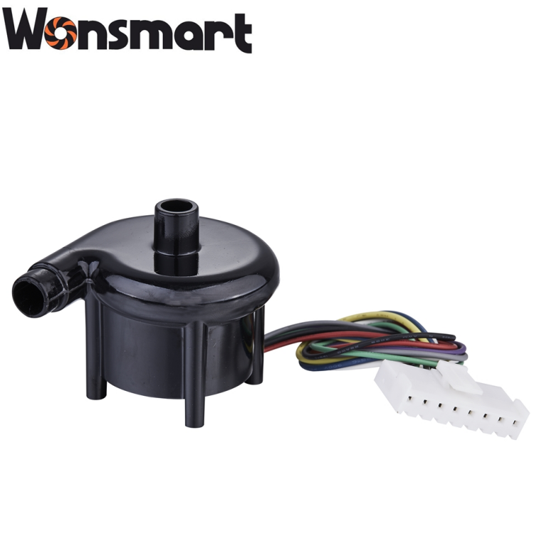
Because pressure and flow are coupled, select a point on the applicable P–Q curve so the proposed circuit demand is actually achievable. P–Q means pressure versus volumetric flow. The relevant curve also needs its supply voltage, speed or command condition, and measurement basis identified.
There is a useful unit check on this page: 7.2 m³/h converts to 120 L/min, while the introductory text says 130 LPM. Resolve that discrepancy in the controlled data sheet. Neither value establishes the flow available at the device’s required pressure.
I would use the published limits to shortlist the model, then use the confirmed curve to make the selection. A curve point should not be inferred by assuming a straight line between the endpoints.
How Do You Build the Required Operating Envelope?
Build an envelope of circuit conditions, including patient-demand simulation and allowed leakage, rather than one nominal steady-flow point. A unit that reaches the target on a fixed restriction may still lack reserve when demand changes.
For a vented CPAP interface, not all escaping flow is a defect. ResMed explains that airflow through the mask vents flushes exhaled air. The device must account for its intended interface and vent behavior; intended vents must not be obstructed to improve an apparent pressure result.
For an illustrative engineering budget only, suppose the simulated patient demand is 30 L/min, the selected interface vents 25 L/min at the chosen pressure, and an additional 10 L/min represents the allowed unintended leak condition. The instantaneous demand would total 65 L/min for that assumed case. These are hypothetical inputs, not Wonsmart ratings or clinical settings.
Because a blower must support flow while maintaining circuit pressure, compare the flow budget with the pressure available at that same condition. A 120 L/min free-flow headline cannot answer whether the assumed 65 L/min condition is supported at the required head.
Add pressure losses through the actual filter, passages, humidifier, and tubing at the relevant flow. Keep blower-outlet pressure distinct from pressure at the therapy measurement location. Document clean-filter and intended service-limit conditions so the design is not evaluated only at its lowest resistance.
What Does PWM Control Actually Give the Device Engineer?
A PWM input provides a command interface only when its electrical and functional definition is known; it is not itself a pressure-regulation specification. Pulse-width modulation can be used in different ways, so the signal description matters.
The WS4540-12-NZ03 page describes an internal controller and speed control. Translate that into an interface review: command range, accepted signal levels, grounding, startup behavior, feedback availability, and response when the command is absent. Do not assume that an external PWM control input permits arbitrary PWM switching of the power supply.
Separate the motor-control loop from the device’s pneumatic loop. The motor drive may regulate commutation or speed, while device software responds to pressure information. Sensor placement, pneumatic delay, command limits, and control tuning all influence the result.
A faster motor response is useful only if the assembled device reaches the required pressure response without unacceptable overshoot or instability. Define a disturbance test with a simulated circuit change, then record the pressure trajectory and electrical behavior together.
I recommend testing more than command steps in open air. Use the intended circuit or an appropriately representative fixture. A response time measured without the pneumatic load should not be presented as pressure recovery under breathing demand.
How Should Low Noise Be Evaluated?
Compare noise at the same operating point and test arrangement; “low noise” without those conditions is not a usable acceptance criterion. A free-running sample and an enclosed, loaded device are different acoustic systems.
Identify whether a reported value is sound pressure or sound power, its weighting, microphone position, background conditions, operating point, and mounting arrangement. A single overall level can also hide a noticeable tonal component. Record the spectrum where the application needs it rather than ranking samples by one unsupported number.
Airflow restrictions, outlet transitions, structural transmission, and enclosure resonances can all contribute to the assembled result. If the bare blower is acceptable but the enclosure develops a tone, investigate the integration path instead of immediately replacing the motor.
Because isolation and silencing can change both airflow resistance and heat rejection, repeat pneumatic and thermal checks so an acoustic improvement does not consume the operating margin. Flexible mounts must still provide appropriate retention and maintain clearances over the intended service conditions.
Choose acoustic materials with the medical gas path and expected aging in mind. A material that absorbs sound effectively is not automatically suitable near air delivered to a patient. Keep cosmetic enclosure treatments distinct from anything that can affect the breathing gas.
Where Do Thermal and Electrical Margins Disappear?
Validate voltage, current, temperature, and pneumatic output together at demanding operating conditions. A nominal supply label does not describe voltage at the blower during acceleration or the thermal condition inside the final enclosure.
| Condition | Observe | Decision |
|---|---|---|
| Demand change | Record pressure recovery and supply behavior. | Decide whether the actuator and power path retain adequate margin. |
| Higher circuit resistance | Record the operating point and temperature trend. | Check the declared circuit envelope rather than the free-flow limit. |
| Enclosed operation | Measure relevant temperatures after stabilization. | Assess airflow, mounting, and heat rejection in the finished arrangement. |
| Low available supply | Check startup and loaded pneumatic performance. | Resolve supply or actuator limitations before software compensation is assumed. |
| Acoustic modification | Recheck pressure losses and heat accumulation. | Approve noise measures only with the other requirements still satisfied. |
Do not assume the maximum electrical load occurs at the maximum static-pressure point. The blower and drive characteristics determine where demanding power and temperature conditions occur. Use the relevant curves and measured behavior rather than applying a generic fan assumption.
Likewise, a component reliability estimate does not establish the device’s service life. Confirm the operating conditions and statistical meaning before using any lifetime figure in a design claim or maintenance plan.
What Does Medical Compliance Require Beyond the Blower?
Component documentation is an input to the medical-device evidence package, not a substitute for device-level safety and essential-performance assessment. Electrical, pneumatic, software, material, and environmental risks interact after integration.
ISO 80601-2-70:2025 addresses sleep-apnoea breathing therapy equipment. Select the applicable standards and recognized editions for the target market and device scope; do not assume that a blower described as suitable for CPAP establishes conformity of the finished system.
For electromagnetic compatibility, IEC 60601-1-2 and its 2020 amendment address electromagnetic disturbances. Evaluate emissions and immunity with the actual controller, harness, power source, enclosure, and operating modes. A quiet-running motor is not evidence of acceptable electromagnetic behavior.
The FDA’s recognition entry for ISO 18562-1:2024 describes biological evaluation of breathing gas pathways and notes partial recognition. Establish the material evidence and evaluation strategy for the actual gas path, including relevant processing and aging conditions. RoHS or REACH documentation answers different questions and cannot replace that assessment.
I would keep these evidence requests specific: material identities, controlled revisions, relevant test coverage, and information needed by the device’s risk process. A folder of unrelated certificates can appear complete while leaving the actual integration questions unanswered.
What Should a CPAP Blower Sample Test Prove?
A sample test should establish that a traceable configuration can meet the intended operating envelope in a representative system. It should do more than show that the impeller spins and pressure rises when the outlet is restricted.
Begin with the CPAP blower product line to shortlist candidates, then prepare the required simultaneous pressure–flow conditions, supply limits, circuit description, space constraints, control interface, and acoustic test basis. This makes model comparison possible without assuming that all listed CPAP blowers serve identical duties.
Record the sample model, hardware revision, firmware or drive configuration where relevant, test fixture, and instruments. Define pass criteria before testing and retain the actual traces. Repeat the evaluation of affected requirements when the mounting, filter, driver settings, or gas-path material changes.
Development tests should use suitable laboratory fixtures and authorized device procedures. A supplier sample is not a finished therapy device for unsupervised patient use.
Frequently Asked Questions
Is a CPAP blower the same as a CPAP machine?
No. It is the air-moving component. The complete device adds sensing, control, circuit interfaces, and the safety functions required by its intended use.
Can maximum flow and maximum pressure be used together?
Not unless the applicable curve establishes that simultaneous point. They commonly describe opposite ends of the blower characteristic.
Why does 7.2 m³/h equal 120 L/min?
Multiply cubic meters by 1,000 to obtain liters, then divide hourly flow by 60. Resolve conflicting published values in the controlled model data before selection.
Does PWM make the blower pressure-controlled?
No. A defined command interface still needs sensing and the appropriate device control architecture to achieve a pressure target.
Can quieting foam be chosen only by acoustic performance?
No. Review its position, material suitability, aging, and possible effects on the gas path, temperature, and pneumatic losses.
Does a blower certificate establish IEC 60601 compliance?
No. Relevant component evidence supports the finished device assessment, but it does not establish compliance of the integrated system.
Turn the Specification Into a Testable Sample Request
The right CPAP blower is the candidate that supports the required pressure–flow envelope and integrates successfully with the device’s control, acoustic, thermal, and safety design. Its strongest specification is a set of testable conditions rather than a pair of maximum numbers.
To request CPAP blower samples, send Wonsmart the operating-point table and representative circuit requirements with the interface and packaging constraints. Ask for the matching curve and controlled configuration, then evaluate the sample against that same brief. This gives engineering and purchasing a common basis for deciding whether to proceed.
Post time: Nov-17-2026


